JARVAS
UWB-based indoor positioning system

JARVAS (Just A Rather Very Average System) is an indoor positioning system, in which a wearable tag communicates with multiple stationary anchors to determine its position.
It was designed as a class project for EE 285 along with Derin Dutz, Quand Nguyen, Eli Wu, and Anna Zeng.
How to Build It
Our primary documentation for how to re-create our setup lives on Instructables.
Source Files
All of our source files (including software, PCB design files, and MATLAB simulation code) live in our GitHub repository.
Technical Details
This website documents some of the more interesting technical aspects of the project. If you’re looking to modify, extend, or get inspiration from what we did, read on.
JARVAS Hardware

The core of the JARVAS system is the DWM1000 ( product page, datasheet ) radio module, an ultra wideband transciever module optimized for time of flight ranging systems, and the Atmega32U4 processor.
There are two versions of the JARVAS hardware: a base station board that supports WiFi (using an ESP8266 ) and is designed for easy debugging, and a small, low-cost tag module. The system requires at least one of the anchors have WiFi support so transmit location data to a server, however all other anchors and tags in the system may use either the larger base station board or the small tag board.
The Tag
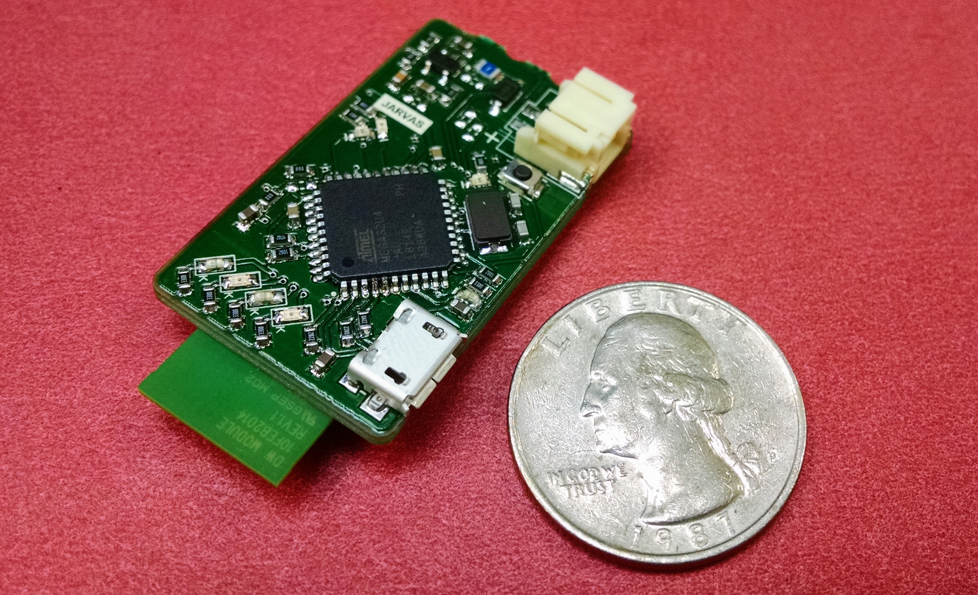
The tag board hosts an Atmega32U4, a single-cell LiPo/Li-Ion connector, a few debugging LEDs, and the DWM1000 radio module. It is essentially a purpose-built version of the popular SparkFun Pro Micro or the Adafruit Atmega32U4 breakout with a DWM1000 module built in.
In total, it measures 1.5”x0.9” without the programming tag.
Note that while we call this this “tag”, it is completely capable of being used as an anchor as well, provided that there is at least one anchor in the system which supports WiFi.
Programming Header

The tag comes with a break-away section for initial programming. The section at the top contains test points for the 3.3 V and GND rails and an ICSP header. This ICSP header can be used to program the Atmega32U4. If you choose to install the Arduino firmware, as described below, you can program this board directly over USB through the Arduino software. Once you verify that everythings is working, this top section can be broken off to reduce the size and height of the PCB.

The Anchor

The anchor is the larger, more debug-friendly, and WiFi-supporting version. It is extremely similar to the tag except for the addition of an ESP8266 WiFi Module and using an off-the-shelf Arduino Pro Micro instead of having an Atmega32U4 on-board. This means that no programmer is required to get this board up and running. The downside, though, is that it is significantly larger and costs more.
Localization
JARVAS estimates your position using a linear least squares algorithm based on time of flight ranging data. On this page, we will break down how this works in detail.
Imagine you are on a ship and can see a single lighthouse in the distance. Let’s say you can tell the distance to this lighthouse but nothing else. If you were looking at a map and knew the location of the lighthouse, you could draw a circle around the lighthouse and know that you were somewhere along the circle.
Now let’s say you can see a second lighthouse and also your know distance to it (but not, let’s pretend, the angle between the two lighthouses). Now you have two circles you can draw. Assuming the two lighthouses are in different locations, the circles will overlap in one or two locations. Finally, by adding a third lighthouse, you can figure out which point you are at.

Linear Least Squares Estimation
If you aren’t familiar with linear least squares estimation, we recommend some background reading before jumping into this:
Wikipedia: Linear Least Squares
Stanford Linear Algebra Course Notes
Our linearized technique is based on the first method described in “Linear least squares localization in sensor networks” by Yue Wang (DOI: 10.1186/s13638-015-0298-1).
In general, localization based on a set of distances in a non-linear problem, however there are linear approximtaions that work quite well.
Each anchor has some known position ((x_i,y_i) and is can measure a distance (\hat{d_i}) to the tag. For a single anchor (i) ranging to a tag at position ((x,y)), this gives us the simple geometric equation:
\[(x-x_i)^2+(y-y_i)^2=d_i^2\]We can then re-arrange this expression as follows:
\[x^2-2xx_i+x_i^2+y^2-2yy_i+y_i^2=\hat{d}_i^2 \\ -2xx_i - 2yy_i + (x^2+y^2) = \hat{d}_i^2 - x_i^2 - y_i^2\]We have three (or more) anchors, so we can write at least three of these equations. Written in matrix form, we have:
\[\begin{bmatrix} -2x_1 & -2y_1 & 1 \\ -2x_2 & -2y_2 & 1 \\ -2x_3 & -2y_3 & 1 \end{bmatrix} \begin{bmatrix} x \\ y \\ x^2 + y^2 \end{bmatrix} = \begin{bmatrix} \hat{d}_1^2-x_1^2-y_1^2 \\ \hat{d}_2^2-x_2^2-y_2^2 \\ \hat{d}_3^2-x_3^2-y_3^2 \end{bmatrix}\]This gives us the standard form:
\[\begin{bmatrix} x \\ y \\ x^2 + y^2 \end{bmatrix}_{ls} = \begin{bmatrix} -2x_1 & -2y_1 & 1 \\ -2x_2 & -2y_2 & 1 \\ -2x_3 & -2y_3 & 1 \end{bmatrix}^\dagger \begin{bmatrix} \hat{d}_1^2-x_1^2-y_1^2 \\ \hat{d}_2^2-x_2^2-y_2^2 \\ \hat{d}_3^2-x_3^2-y_3^2 \end{bmatrix}\]The left side of the equation is what we want to solve for. Specifically, we are interested in the first two terms of the vector: (x) and (y).
On the right, the large matrix that we have to take the pseudo-inverse of is a function only of the configuration of the system. It changes only if the anchors move, not if the tag moves. This is very important because taking the pseudo-inverse requires a non-trivial number of computations, especially as you start adding more anchors.
At runtime, this works out to be a single matrix-vector multiplication of a 3x3 by a 3x1.
MATLAB Implementation

In order to test this algorith, we created a MATLAB script that takes in a set of positions and ranges and outputs a graph of the real and estimated location of the tag. If you are intersted in extending this project to use any of several possible better linearized algorithms, this MATLAB script would be a good starting point.
You can find the two MATLAB files rangepositioning.m and plotposition.m in the simulation folder of our repository.
C Implementation
In the JARVAS system, this processing is run on the tag iself. The C implementaiton of this algorithm uses the Arduino MatrixMath library and lives in the tag sketch.
Filtering
In our testing, we found the ranging data to be quite noisy. With only three anchors, the linear least squares algorithm is quite noise sensitive. As such, some filtering on the ranging data is necessary.
The Arduino DWM1000 library by thotro has a built-in exponential moving average filter that can be enabled with a single call to DW1000Ranging.useRangeFilter(true);. This is a very computationally low-cost choice and definitely a good place to start.
Early on, we took some raw data from pairs of DWM1000 modules in various locations. An example of this data is below:

As you can see, the noise is dominated by sharp peaks lasting only a sample or two. For this type of noise, a median filter is often a more effective choice. While any kind of moving average filter is always going to be affected at least a little by an extremely out of range value, a median filter will allow such valus to slide through without changing output.
Shown below are the results of a simple median filter overlayed in red against another raw data set in black.

Programming Arduino Firmware on an Atmega32U4
This page is not really specific to this project and should be useful to anyone trying to program Arduino firmware onto an Atmega32U4 chip.
What you’ll need
You will need:
- An ICSP programmer (such as the JTAGICE3)
- The avrdude software
- Firmware for the chip. We used SparkFun’s Caterina bootloader (Caterina-promicro8.bin from here)
- A board with an Atmega32U4 and an ICSP header, such as our Tag Board
Tip for Linux users
You may need to setup port permission for your programmer. For the JTAGICE3, you’ll need to create a /etc/udev/rules.d/98-local-jtagice3.rules file with the following line:
SUBSYSTEM=="usb", ATTRS{idVendor}=="03eb", ATTRS{idProduct}=="2140", GROUP="dialout"
Also, be sure your user is in the dialout group.
Instructions

Step 1: Hook up your programmer
Connect your programmer to the ICSP header on your board. Double check the pinouts and orientations (many ICSP connectors are not keyed) before powering things up.
Remember that your programmer generally does not supply power to the board, so you’ll need to supply that yourself.
Step 2: Test the connection
The following command will read the three sets of fuse bits from the microcontroller and write the values to three text files on your system:
avrdude -v -pm32u4 -cjtag3isp -Pusb -B22 -U efuse:r:efuse.hex:h -U hfuse:r:hfuse.hex:h -U lfuse:r:lfuse.hex:h
You should get some output that ends with:
avrdude: safemode: hfuse reads as 99
avrdude: safemode: efuse reads as F3
avrdude: safemode: Fuses OK (E:F3, H:99, L:5E)

avrdude done.  Thank you.
Step 3: Programming
With the firmware file placed in your working directory, run the following command to set the fuse bits and program your chip:
avrdude -v -pm32u4 -cjtag3isp -Pusb -B22 -U flash:w:Caterina-promicro8.hex -U hfuse:w:0xd8:m -U lfuse:w:0xff:m -U efuse:w:0xfe:m
It may fail to write the efuse. If prompted, answer ‘y’ to retry. If it fails, don’t worry.
Step 4: Try it!
Plug your board into your computer over USB and program it with the Arduino software.
Notes and References
The above commands assume you’re using a JTAGICE3 programmer to program an Atmega32U4 clocekd at 8 MHz with a 3.3V supply voltage. If any of those things are not quite the same for you, you’ll have to adjust things a bit.
You can find fuse bit settings that go along with the various SparkFun firmwares on their repository.
Useful References
- Fuse bit calculator
- JTAGICE3 Pinout
- AVRDUDE Refernce
- A blog post from someone else who has done this